|
Pre-amplifier Boards
Looking at side of pickup assembly that faces film. Photo-transistors at right connect to circuit board on the underside of the bracket. The top side circuit board has the second transistor stage for left and right channels. The coupling capacitors that connect the output of the underside board to the input of the top side board feed through holes in the bracket. |
 |
 |
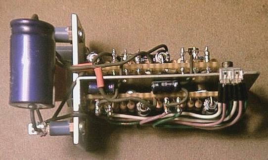
View of underside. Plenty of slack on wires from photo-transistors to reduce stress on the fragile wire leads
of the photo-transistors. |
|
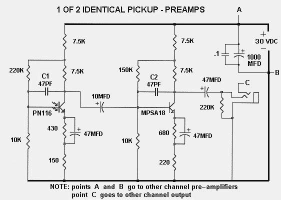
Circuit used for photo-transistor pickup. C1 and C2 are compensation capacitors and very important as they prevent high frequency oscillations that add distortion to the sound. The emitter circuit uses dual resistors with only one resistor bypassed and provides reduced low frequency distortion. |
|
|
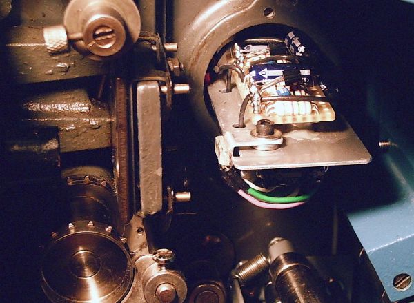
The pickup assembly installed on the projector, photo-transistors set to proper position. |
|
The pick-up / pre-amplifier assembly fits in the same space as the original photocell. Construction of the
assembly with pre-amplifiers requires a fair amount of expertise. The assembly as shown above just fits
through the old photocell socket hole as installed from the back side of the projector. The hand made
circuit boards must be small and parts laid out carefully. Construction like this should only be attempted
by someone experienced with electronics. |
|
The small bracket that the photo-transistors are glued to is adjustable. The photo-transistors must be all
the way back against the main bracket when installed through the old cell socket hole. Once the pick-up
assembly is screwed in place, the photo-transistors can be positioned as close as possible to the cover
hole. |
|
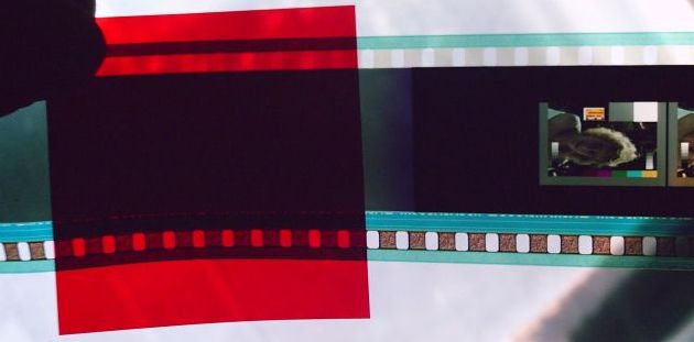
The motion picture industry switched from silver black optical sound tracks to dye green sound tracks to save
money on print cost. Green dye tracks let light through and if scanned on a traditional white sound scanner
will produce lower level audio with higher background noise. Green tracks must be scanned with a red sound reader.
Looking at the picture below, the green track is darkened were the red filter is placed. |