|
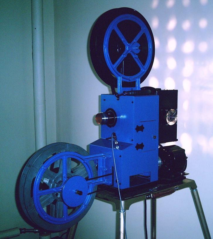
THE PROJECTOR was completely taken apart and gone through as described in the following paragraphs. Several
modifications were incorporated. The case paint was stripped and repainted with a now discontinued industrial
quality RUST-OLEUM epoxy paint that came in spray cans. The case was painted in 1993 and so far has resisted
chipping. The projector inside the case is still the original gray.
THE GEARBOX is still original, the only work I did here was to clean out all the old grease and re-pack with
new grease. Re-packing the grease was the first thing I did using axle grease around 1991. I replaced the grease
in the gear box recently with grease made by the same folks who make Slick50. This grease has Teflon in it and
seems to be less oily than other grease. So far I haven't had any oil drip from the gearbox.
GEARBOX PICTURES
THE SOUND ROLLER'S, the two roller's before the sound gate in the original Holmes design are fixed in
position. Being fixed, there is no way to keep the film tight through the film path from the sprocket after the
intermittent to the sound gate. This causes a couple problems. Depending on the slack, the film rides up some
off the sprocket after the intermittent. Also, if there is too much slack, the film jumps off the back end of the roller
before the sound gate. The back end of the roller before the sound gate has a spring in it to keep the film
positioned properly in the sound gate.
To correct this problem, an adaptor for one of the roller's was fabricated allowing the roller to be spring loaded
and compensate for slack in the film.
ROLLER ADAPTOR PICTURES
THE OLD FIRE ROLLER'S for the feed and takeup reels were modified so that thick splices will pass. The original
roller's were very close and thick splices would not pass.
FIRE ROLLER MODIFICATION PICTURES
TAKEUP ROLLER MODIFICATION added to the projector to absorb the shock from the takeup reel jerking the film
from the last sprocket. Different factors such as how loose the takeup belt is or if the takeup reel is full
and you are restarting the projector can cause the takeup reel to hesitate for a moment on start-up. This
causes the film to slightly slack off the last sprocket and then get jerked as the takeup reel gets up speed.
This can snap old brittle film so a spring loaded roller assembly was fabricated and added to absorb any
shock from the film being jerked by the takeup reel.
TAKEUP ROLLER MODIFICATION
THE SOUND PICKUP has been modified with the old photocell being replaced with a stereo
photo-transistor pickup. The photo-transistors are mounted to a small metal bracket that mounts from the
back side of the projector, through the old photocell socket hole.
PHOTO-TRANSISTOR PICKUP PICTURES
THE PRE-AMPS for the pickup are mounted to the same bracket as the photo-transistor pickup.
The photo-transistors double as the sound pickup and first stage of amplification. A second transistor follows
the photo-transistors for a total of 55db of gain. The sound output is in the front of the projector like original
but with a stereo (3-circuit) jack.
There are two small hand made circuit boards, one has all parts for the photo-transistor electronics and
the other has the electronics for the second transistor stages. The circuit board for the photo-transistors
is mounted on the underside of the bracket. The circuit board with the second stages is mounted on the
top side of the bracket. It is fairly tight but there is plenty of room for the original cell cover to fit over the
new assembly.
PRE-AMP PICTURES AND SCHEMATIC
THE SOUND PICKUP COVER is the original photocell cover. The stereo photo-transistors are positioned at the
cover hole. The photo-transistors are about 3/4 inch from the film. The scan beam from the soundtrack spreads
as it leaves the film. The separation between the photo-transistors is right for the amount of beam spread at
this distance.
Because of the beam spread, a vertical divider is used between the photo-transistor to help keep the left and right
channel beams from completely crossing each other. The cover is modified with a hood that holds a vertical divider
attached to the cover opening. Because the sound gate needs room to open, the vertical divider is about 2/5 inch from
the film so there is some beam spread cross-over before it reaches the divider. The added hood also helps shield the
photo-transistors from stray light.
PICKUP COVER PICTURES
THE LAMP HOUSE has several changes. First I wanted to replace the original 1000 watt bulb with
a lamp that was less expensive to replace. Besides the high cost of replacing those old original lamps, the
original reflector had no silver left on it. I decided to go with an ELH 300 watt lamp which has a self contained
reflector and operates on 120VAC. Although the new lamp won't fill a 20 foot screen, it is plenty bright for the
6 foot picture at home.
Another change to the Lamp House was to get rid of the belt driven blower and asbestos heat shield. I
constructed a new Lamp House cover with a built on box fan blower. The new cover is made of 14 gauge
steel and much more sturdy than the original.
An addition to the Lamp House is the exciter lamp power supply. I wanted the projector to have a self
contained exciter supply and sound pre-amp. Since space is so tight, I decided to use a single supply
for both the 4V exciter lamp and the 28V sound pre-amp. The large filter capacitors and voltage dropping
resistors I mounted on a plate in the bottom of the Lamp House.
LAMP HOUSE PICTURES
THE EXCITER LAMP was changed to a lower current type to reduce the size of the needed power
supply. Also, the newer lamp has a thinner filament which provides a thinner scan line for a better high
end response. It is a BAK 4-volt .75 amp lamp. Although the new exciter lamp generates less light then the
original exciter, the original photocell has been replaced with photo-transistor pickups that require less
light. I found that the original exciter lamp socket holds the new lamp good and alignment works well.
EXCITER LAMP PICTURES
THE SWITCH BOX containing the threading light, motor and lamp switches has also been modified.
The circuit has been changed and includes single pole switches for motor and lamp, a fuse for the motor
and lamp circuits, a transformer & rectifier for the exciter lamp & sound pre-amp and a power cord
with a three prong AC plug for ground.
The new transformer is mounted on the back side of the switch box enclosure. Terminal strips have been
mounted inside the box for the rectifier circuit and all projector circuits to terminate. The new fuse is
mounted inside the box but removing the cover provides easy access to the fuse.
Ground wires run throughout the projector grounding the motor, Lamp House, switch box and projector
case.
The original power cord and lamp sockets on the switch box have been removed. A new plate has been
fabricated and installed on the switch box in place of the old connectors. Large holes and rubber
grommet's provide holes for the AC cord and Lamp House wiring harness.
SWITCH BOX PICTURES
THE FILM GATE has been modified so aperture plates can be inserted. This is mainly for the
newer aspect ratio of flat movies. For older prints the aperture plate is removed and the original
aperture is used.
The film gate is made out of hardened steel and a file won't work so the original aperture remains.
For cinemascope, the picture will be cut off a little at the top and bottom so it'll be a really wide picture.
FILM GATE PICTURES
THE MAIN DRIVE ball bearings went out on me. When I tried looking for new bearings I could not find
exact replacements with the tapered offset. Instead, I purchased standard flat ball bearings and then added
flat bearing washers to the main drive gear. I found no real need for the tapered bearings, the flat bearings
clear the main drive gear housing fine. The washers I added position the main drive gear for proper mesh.
MAIN DRIVE GEAR PICTURES
THE CUSTOM AMPLIFIER is a new 3-channel, 10 watt per channel solid state amplifier. The original tube type amplifier
was in very bad shape and with the new stereo pickup a stereo amplifier was needed. The three channels are
left, right and sub-woofer used to drive a bass speaker.
CUSTOM AMPLIFIER
|