
A Low Cost Speaker Project
Having already written too much about amplifiers I decided, for a change, to add a speaker design section. None of the ideas tried are intended to be highly original, this is just a 'fun project'. An experimental approach will be used, with a minimum of theory and analysis. The idea is to try different options to see how they sound and measure before deciding what works best. (i.e. 'trial and error').
To keep cost and complexity low I wanted to use a full-range drive unit. A previous enclosure I tried had space for only an 8cm unit, so although that design was eventually abandoned it determined the speaker chosen. Fortunately there are a few good quality 8cm full-range drive units available from Visaton, Tangband, Fostex, Aurasound, etc. Some of these are too expensive to qualify for a 'low cost' project, but the Visaton FRS8 (4ohms, model 2003), while unlikely to be the best possible, is both cheap and highly regarded. Some of the others need notch filters to reduce response peaks but, if the manufacturer's specifications can be trusted, the Visaton is reasonably flat up to 10kHz without such additions, with a few moderate peaks and dips from 10kHz to 20kHz where the effect should be less audible. There may have been a change of specification, with the current Visaton website (Oct. 2006) listing resonant frequency 115Hz, Vas 1L, and Qts 0.69, while other sources, possibly out of date, say 130Hz, 0.8L, and 1.07 respectively.


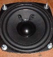
Here is the Visaton FRS8, model no.2003, bought from BMM Electronics in Holland. There are various 'tweaks' which could be applied before fitting the speaker, for example applying a thick coating of 'Blu-Tak' or 'Sello-Tak' to the speaker frame to damp its resonances, as shown above on the right. An example of this and other possibilities were shown on DiyAudio. Using a screwdriver to tap the outer metal edge of the speaker with damped frame, it sounded very dead in comparison to an unmodified speaker. This is no guarantee that there will be any audible improvement in the finished design, but it seems unlikely to do any harm, and the Sellotak only cost 99p for enough to treat at least five speakers.
Measuring resonant frequency, fs, of this speaker gave a result near to 150Hz, higher than either the old 130Hz or the new 115Hz specification. It can be expected that the value will fall after extended use, but this was still a little discouraging. I decided to leave the speaker with a 2V rms 20Hz sine-wave applied for a few hours and retest to see the extent of the fall. I have no reason to believe 20Hz is the best frequency to use, but it can give a large cone movement while being inaudible. After 3 hours fs was 128Hz, after 4 hours 120Hz, and finally after 5 hours the specified figure of 115Hz. It occurred to me that the temperature of the suspension will rise with extended use, which may cause a change in fs, so I left the speaker disconnected for an hour and measured again, now finding fs to have risen to 121Hz. Whatever the reason, fs is clearly somewhat variable, and there is little point trying to be too exact about its value, though it may settle down to a more constant frequency eventually. This sort of variation is well known, not unique to the FRS8.
A rectangular sealed wooden box used as an enclosure has some well known problems, for example the flat parallel internal surfaces can cause resonances, and the sharp edges can cause diffraction effects. Using a curved enclosure can reduce these effects, but making one is difficult, so for the first project I started looking for something ready-made which could be adapted.
The first possibility I found is a small wooden fruit-bowl, bought from our local Morrison's supermarket for only £2.99 (UK). The maximum outside diameter is 8 inches (20.4 cm) and the height 5.5 inches (14 cm), the wall thickness is about 7/16 inch (1 cm) and the internal volume 2.2 litres.
The first idea was to cut a circular hole in the base to mount a suitable drive unit, but initial experiments resulted in such an unpleasant sound that this was quickly abandoned, and instead a flat front panel used, with a bowl forming the back of the enclosure.Since then I also found hollow steel spheres available from Homebase, with diameters 24cm and 32cm, giving volumes 7.2 and 17 litres respectively. (The smaller size was £12.99.) These appear to be intended as garden ornaments, and have a small flat section for them to stand on, which could be cut out to fix a fullrange driver. A few examples of spherical metal enclosures can be found, e.g. on DiyAudio, but a wooden enclosure is more suitable for the sort of experiments I wanted to try, so the first project used the wooden bowl as part of a 'distributed port' enclosure :
A Distributed Port Speaker
The first type of enclosure I ever built many years ago was a 'distributed port reflex', which in one form has a number of small holes on the front panel instead of a single large reflex vent. Using 5mm diameter holes in a 25mm panel with a 2 litre enclosure the Helmholtz resonator frequency can be worked out. If we assume that, apart from greater resistive damping, a number of separate vents have the same effect as a single vent with the same total area (which is widely believed, though I have never been entirely convinced), then the approximate resonant frequencies for different numbers of holes are:
HOLES....FREQUENCY
....24.........126Hz
....20.........117Hz
....16.........107Hz
....12..........95Hz
.....8..........80Hz
.....4..........60Hz
.....2..........44Hz
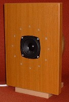
These figures are probably very inaccurate, because the effective length of a vent is a little greater than the measured length, and I am uncertain how this end correction should be calculated for distributed ports, and just used an on-line Helmholtz resonance calculator. Accuracy is not really essential however, the idea being to start with a large number of holes so that some of them can be blocked to find the effect of different numbers.The front panel to be used is 30cm x 22.5cm x 2.5cm thick. The first thing to be done is to cut a 76mm diameter hole for the speaker. The FRS8 specification says it needs a 72 to 73mm diameter hole, but I found that they fit flatter with something near 76mm diameter. This is shown next, the 5mm holes being on a 14cm diameter circle, arranged symmetrically round the speaker cutout, and initially I used just 12 holes. The speaker cutout is filed outwards to give better air-flow behind the drive unit. (But see later for a problem caused by this approach.) The stand is then drilled and fixed in place with long screws into the bottom edge of the front panel.


When the bowl is glued in place to cover the back of the speaker the ring of 5mm holes will open into the interior of the enclosure. The bowl can be lightly filled with sound absorbent material (I used Visaton lamb's wool), and a thin cloth covering is used to prevent the wool getting into the back of the drive unit, shown below left. A groove must be cut in the bowl for the speaker cable to pass through, below right, and small metal brackets are used to attach the bowl to the back of the front panel.


After adding the absorbent material and threading the cable through to the speaker opening the bowl van be screwed and glued in place. I used Copydex glue, which is non-permanent. If permanent glue is to be used the metal brackets are not essential and can be omitted.


Initial listening tests suggested that the result was much better than a previous version with the speaker in the narrow end of the bowl. Something was still not right, and experimenting with a graphic equaliser I found that reducing the output around 2kHz gave some improvement. There appeared to be little low bass, though listening to sine-waves revealed clearly audible output down to 60Hz, below which it rapidly vanished. Blocking any of the twelve 5mm holes I initially thought gave a reduction of output from a 60Hz input, so later tests used a maximum of 24.
First the low frequency output was observed using a microphone to check distortion levels, and the first three results shown next are at 100Hz, 70Hz and 60Hz, all at the same signal voltage. The shape is good at 100Hz, has deteriorated at 70Hz, and is very poor at 60Hz. This depends on level, but it shows how distortion can rise at lower frequencies because of greater cone excursion. The fourth picture is for a 100Hz square-wave input. Few speakers can produce anything remotely like a square-wave, so this is no surprise, but it shows how pointless it is to worry about a few degrees phase error from an amplifier.


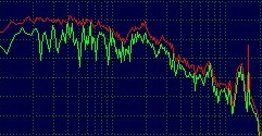
The next photo is the frequency response obtained in a medium size room with the speaker on a small table well away from the walls. The red trace is a peak-hold function obtained after sweeping the frequency from 40Hz up to 600Hz, and the green trace is the output at 600Hz, showing the second harmonic at about -46dB. Blocking a few of the front panel holes had surprisingly little effect, maybe one or two dB variation, suggesting that this distributed port reflex is fairly uncritical.


The second picture above is with a pink noise input (which rises at 3dB per octave with falling frequency, and should give a rising bass output), and shows that something is happening around 2kHz, as guessed from the initial listening test. The variation may fit within +/- 3dB limits, but having noticed it so easily in the first listening impression it seems worth investigating further. Blocking all the vent holes had no effect near 2kHz, and adding more absorbent material, about three times the original amount, again had little if any effect. Having abandoned the curved front from an earlier version it could be that baffle edge diffraction is involved, but adding an extension to the front panel had only a small effect around the 2kHz region. The next step was to remove the bowl altogether and test the speaker as an open-baffle. The result is shown below left, again using pink noise, and the 2kHz problem is still there.


I then checked the sound from the back of the speaker, shown on the right. This was a surprise, the output dropping sharply by over 20dB just above 2kHz. A fall at high frequencies would be expected because of the obstruction from the frame and magnet, but this is far sharper than I would have expected. The first guess was that the 25mm thick panel, together with the flared shape used to improve air flow, somehow cause this problem, which then also has a smaller but still audible effect on the sound from the front of the speaker. The next step was to try a thin baffle, using a 2mm thick sheet of hardboard 42cm x 32cm, to find out if the thickness is really the source of the problem. The drive unit without a baffle was also tested, with results shown next:
This is at the front of the speaker without a baffle.
This is at the back of the speaker without a baffle.
This is at the front with the 2mm thick 42cm x 32cm baffle.
This is at the back with the 2mm baffle.
Looking at the red peak-hold traces, there are still some small variations, but the sharp 20dB drop at the back of the speaker has vanished. This seems fairly conclusive, the drive unit is not happy with a thick baffle, even when this is flared outwards as often recommended. To check further the speaker with thin baffle was listened to, and now reducing output at 2kHz with a graphic equaliser no longer seemed to be an obvious improvement.
If the drive unit is sensitive to panel thickness it may also be affected by whether it is fixed from the front or the back, as shown next with corresponding pink noise outputs from back (left) and front (right) :


The difference is fairly small but clear and repeatable, and in both cases there is still a dip around 2kHz, but I think the second arrangement with front mounted speaker looks a little smoother. I heard no immediately obvious difference in the sound, but there is one great advantage to using the front mounted driver, which is that it can be removed even if the enclosure is completely sealed. With a thin panel the speaker is most easily fixed with nuts and bolts, and then the bolts need to be glued in position from inside the cabinet, with the nuts outside as in the photos. Shorter bolts will make this look neater.
Modifications were done next, based on the initial findings, with the number of vent holes increased to 24 and the speaker cutout made as big as possible, with a thin board added to bolt the speaker on. The final arrangement is shown next followed by the pink-noise response using 8 vent holes in two groups of 4, one group at each side of the speaker, all the other holes being blocked on the inside with 'Sellotak' :


The number of vent holes was found to be very non-critical, the sound level at 60Hz was a maximum for 3 to 6 holes, but was only 1dB lower with 8, while 3rd harmonic distortion was 5dB lower with 8 holes than with 3, so 8 seems a reasonable compromise. With more than 8 holes the sound level at 60Hz fell, while both 2nd and 3rd harmonics increased.
The pink noise response still shows a dip around 2kHz, and with different microphone positions the shape of the dip changed, suggesting a cancellation effect, possibly a combination of edge diffraction, internal resonance and port output. The unpleasant sound of the previous 2kHz problem appears to be absent now, and having listened to this final version for a few weeks I am happy with the sound. My impression is that it is far better than my cheap Harman/Kardon computer speakers, which use a very similar 8cm drive unit, better than some cheap Aiwa speakers I also use with my computer, and even comparable to my Mordaunt-Short MS20s on some types of music, for example the guitar intro on 'Hotel California', but more complex pieces can become a little more muddled. Although bass is not extended very low, with positioning on a shelf about 30cm from a wall the bass is surprisingly clear for such a small speaker, and not unpleasantly resonant like some small reflex types. Used as a computer speaker, driven by one of my MJR-7 mosfet amplifiers, the sound can be startlingly clear.
This speaker is really just an experiment, to learn a little about speaker design and try different ways to measure the response, so I hesitate to recommend it. On the plus side the distributed port design is far less critical than conventional reflex ports, and perhaps deserves to be more popular. The original idea to make a more 'spherical' enclosure now seems misguided, though there are published DIY and also commercial designs of this type which are claimed to work well. Any sort of symmetry I suggest is potentially a bad idea, and to avoid the problems of a rectangular enclosure it may be better to use triangular shapes rather than circular.
A more extended bass response appears to be possible using resonant pipe enclosures, and several published designs are suitable for the FRS8, so I may try a few variations to compare the results. Maybe using a triangular shape, something like the Mk2 version of the Bailey transmission-line speaker from 1972, but smaller and with fewer bends, and with the drive unit further along the line as in the 'quarter wave pipe' variety.
