Adding a small inductor in series with the output of a power amplifier may sometimes be necessary to ensure stability of the overall feedback loop with a range of capacitive loads. The inductor plus capacitor load then form a series resonant LC circuit which can have a very small total series impedance at the resonant frequency. To reduce this effect a damping resistor is usually added in parallel with the inductor.
In the next diagram the open-loop output impedance is shown as an external 2 ohm resistor, this being a typical value for a lateral mosfet output stage at quiescent current 100mA as used in my MJR7 design. This impedance is not a fixed value, it will fall in value as the output current increases because of the increase in mosfet gm at higher drain currents. The overall feedback is taken from a point before the inductor.
Vo is the open-circuit output voltage, and Vf is the output voltage with load connected. Suppose Vo is 10V, then Vf is reduced by the load impedance. For the next diagram Vf is shown as a function of frequency. For this example the load capacitor is 2uF and the inductor is 0.4uH. Vf is plotted for two different values of damping resistor Rp, these being 8 ohms and 0.33 ohms.
At very high frequencies the total load is close to the value of the damping resistor. An 8 ohm value is sometimes used in order to maintain the nominal 8 ohm speaker load impedance up to high frequencies with capacitive loads, while the usual RC Zobel network with 8 ohms in series with something around 0.1uF maintains the 8 ohm load impedance for inductive loads. Unfortunately an 8 ohm damping resistor is far too high for critical damping with a 2uF load, and it can be seen from the green trace that there is a notch in the output voltage around 180kHz. Reducing the damping resistor to about 0.33 ohms is just about sufficient to avoid a gain notch, as in the red trace, and this also reduces the output voltage by a factor of 7 at high frequencies. Keeping the 0.33 ohm resistor but increasing the load above 2uF will again result in a notch in the gain, while reducing it below 2uF gives an over-damped result with no notch.
The phase shifts associated with the load effect are shown next, and it can be seen that both add a phase lag around 100kHz, the underdamped version being worse in this respect by almost 20 degrees.
So far we have only looked at the effect of the load on output stage gain. In a complete amplifier there is usually overall feedback and a -6dB / octave compensation. The next diagram combines the underdamped inductor effect with the compensation to show the loop gain as a function of frequency. Low frequency loop gain is taken as 60dB. Unity gain is shown by a blue line.
This result reveals another potential problem of using an underdamped inductor. The unity gain frequency is where instability can occur if the added phase lag round the feedback loop reaches 180 deg. In this diagram there are 3 unity gain frequencies shown as f1, f2 and f3. There is no problem at f2 because the output load adds a phase advance at this frequency, but at f1, around 180kHz, there is 80 deg phase lag added by the load. The amplifier compensation will add more phase lag, and so there is some danger of instability at this frequency. At f3 there is the usual high frequency unity gain frequency, here just over 2MHz, and here again there may be several sources of phase shift which can be a problem. We now need to worry about stability at two different frequencies instead of the usual one. This particular problem can be reduced by using sufficiently high feedback loop gain at 180kHz so that the low load impedance at this frequency is not sufficient to reduce the loop gain to anywhere near unity. Near clipping the loop gain will fall, so there could then still be a problem.
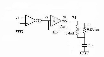
Although it appeared from the results so far that using a critically damped inductor is the best solution for driving capacitive loads, there are other difficulties to consider. With the 0.33 ohm damping resistor the amplifier load is around this value at high frequencies, and the output stage gain is therefore reduced as shown in the second diagram on this page. Consider the circuit shown next in simplified form driving a 2uF load:
This circuit uses a conventional source-follower output stage with series inductor to reduce capacitive load effects, and without any added high frequency compensation. The output stage is driven from a high impedance, as a 'worst-case' example.
The output stage is represented by a unity gain stage with a 2 ohm output impedance, and the total combined mosfet gate-source capacitance, Cgs, is shown as 1500pF. Both output impedance and Cgs vary with output current level, and the values shown are about the worst case for the lateral mosfets used at Iq = 100mA. With an ideal current source driver stage the open-loop gain of the amplifier is proportional to the input impedance of the output stage, which is not just the impedance of Cgs because the full driver stage output voltage does not appear across this capacitor, only a reduced value determined by the potential divider formed by the 2 ohm output impedance and the load, and so we may expect the effective input capacitance to be fairly low at low frequencies, but increase with increased frequency because of the falling load impedance.
The potential divider just mentioned is not however a resistive divider because the load has a reactive component, and so it does not just reduce the voltage across Cgs, it also changes its phase, so the effect is something more complex than just an increase in capacitance at higher frequencies. With a fixed capacitance the resulting open-loop gain reduction would be just -6dB/octave, but with this increasing capacitance the rate is greater. The phase shift of a pure capacitance, even if it had different values at different frequencies, would be 90 degrees, but the input impedance of the output stage is not just a pure capacitance, and adds a phase shift which can approach 180 degrees with consequent risk of instability. For the phase shift to actually reach 180 deg. the input impedance of the output stage would need to be a negative resistance rather than a capacitance.
To see the extent of the problem the phase shift was plotted using AIM-Spice, and the next diagram shows the phase shift at input, V2 in red, and output, V4 in green.
The phase shift at the input of the output stage is the red trace, and this reaches a maximum in excess of 160 deg between 6kHz and 10kHz. This is not what we would expect if our mosfet output stage has a capacitive input impedance, the phase shift could then only reach 90 deg. There is evidently a negative resistance component also. (This is not a consequence of using an output inductor, it is still present with this shorted. The capacitive load is the problem.)
The negative resistance is not itself a serious problem because it has a series capacitance, but if the output stage were to be driven from an inductive source so that the capacitance is cancelled at some frequency then the result would be similar to a Colpitts oscillator, and oscillation is then possible. If wiring inductance is kept low this should not be a problem, but the effect of the phase shift on loop stability may still be important.From this we can conclude that driving a mosfet output stage from a high impedance is not ideal, and the inclusion of an emitter follower stage as in the MJR7 is helpful.