Coil Gun Kit Instructions
Email: sixmhz@yahoo.comLink to my Homepage
Introduction
These step-by-step instruction were designed for the coil gun kit offered on the
Stuff for Sale page. If you purchased this kit, you should have all the necessary parts to complete this project
with the exception of tools and other building equipment.
|
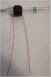 
Step 1. Winding up a Coil
With a bit of super glue, secure a section of the magnet wire to the pipette leaving a few inches of extra wire
sticking out as a connection point. The placement of this coil should be near one end of the pipette, allowing easy
access to it for positioning the projectile. Now wind a single layer of the coil neatly up the pipette, approximately
0.5 inches long. Now secure this layer of the coil in place with a dab more super glue. When the glue is dry, wind the
next layer on top of the first layer back towards where the first one started. Repeat this until there are 5 layers of
windings. Glue everything in place and cut the wire leaving a few inches of extra for connection to the circuit. You may
also want to wrap the entire coil with some electrical tape to make sure everything stays put. Now take a sharp knife and
scrape off the enamel insulation from the two leads that you have left for connection. Sometimes the enamel coating is clear,
so it may be difficult to determine if it is gone. To find out, try measuring continuity (ohms) across your coil's leads.
If you have removed adequate insulation and made good contact, the resistance should be only and ohm or two.
|
|

Step 2. Modifying the Camera Circuit
Essentially all the circuitry for this project can be found (and used) already made inside a typical disposable camera
flash circuit. The camera brand/model will vary with the kit, but operation is the same for all. Start off by CAREFULLY
removing the back cover from the camera. There should be a few plastic tabs around the perimeter of the camera that you
would need to pry loose with a flat-head screwdriver. Once the back cover is off, you need to remove the battery. It is
important that you do this first if you do not want to be shocked. Once the battery is removed, you need to manually discharge
the capacitor to ensure that it doesn't have a stored charge on it. This is done by taking a screwdriver with an insulated
handle and shorting the leads together. Now it is time to remove the entire circuit board from the plastic casing.
|
|
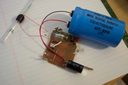
 Once you have removed the circuit board, try to figure out how the circuit worked in the camera i.e. charging up the
and make the flash work. Usually, there is a "charge" button on the front of the camera (red arrow) which when pressed begins the
charging cycle. As for triggering the flash there is generally a mechanical switch in the camera so that when the shutter
flings open it somehow triggers the flash. But now we have no shutter, so we must jumper these switch terminals (short them
together) to make the flash go. These two terminals are usually some bulk metal pieces (black arrows in photo) that used to attach to the shutter
system. So put your battery back in (carefully) and test charging and discharging the flash. If you can't get it to work
here, it will never work in the completed project. Once you are satisfied with this, remove the battery and short out the
capacitor with your screwdriver again. You may want to solder an actual switch in the place of the old shutter mechanism
to trigger the flash, buy you don't have to.
Once you have removed the circuit board, try to figure out how the circuit worked in the camera i.e. charging up the
and make the flash work. Usually, there is a "charge" button on the front of the camera (red arrow) which when pressed begins the
charging cycle. As for triggering the flash there is generally a mechanical switch in the camera so that when the shutter
flings open it somehow triggers the flash. But now we have no shutter, so we must jumper these switch terminals (short them
together) to make the flash go. These two terminals are usually some bulk metal pieces (black arrows in photo) that used to attach to the shutter
system. So put your battery back in (carefully) and test charging and discharging the flash. If you can't get it to work
here, it will never work in the completed project. Once you are satisfied with this, remove the battery and short out the
capacitor with your screwdriver again. You may want to solder an actual switch in the place of the old shutter mechanism
to trigger the flash, buy you don't have to.
|
|

Step 3. Connecting the Coil to the Camera Flash Circuit
There is only one simple connection to the camera flash circuit. Carefully unsolder one of the leads that connect to the
ends of the flash tube. Now take this lead and solder to one of your coil leads that you stripped. Solder your other stripped
lead to the flash tube end that you unsoldered from before. Now when you test your charging and discharging, you should see
that the coil in the circuit has little influence on the flash operation.
Connecting the coil this way allows us to use the existing flash tube as a "trigatron" to switch the high voltage and current.
If we were to use a regular switch, the switch wouldn't last very long.
|
|
Step 4. Adding additional Capacitors
If you purchased the optional capacitors with the kit, you may use them for a multi-stage gun (not covered here) or you can
put one or more of them in parallel with the capacitor in the camera flash circuit for more powerful single stage coil gun.
These capacitors are electrolytic, which means that they have polarity requirements. They have a positive and a negative
terminal. To add them in parallel, simply hook the positive terminal to the positive terminal of the flash capacitor and
the same for the negative terminal. The flash capacitor should have some sort of marking on it indicating which is the positive
terminal. Often times it is marked with a stripe printed on the side of the capacitor leading to the negative terminal.
Step 5. Testing Out Your Coil Gun
If you have followed the above steps and everything has worked out right, now it is time to fire off you coil gun! Take the
projectile and place it inside the pipette so that the end of it is just poking inside the end of the coil. This will be the
back end of the gun, the projectile will be pulled toward and through the coil so point it in a good direction. Now charge
the circuit and hit the fire switch. You projectile should be launched through the barrel and out the other end. You may
have to play with the projectile starting position a bit to reach optimal launching speeds. Keep in mind that this is a
relatively low power system. If you are using all three of the optional capacitors charged to three hundred volts, the
energy stored in this system is approximately 20 joules.
So What's Next?
Well this is only the beginning. Once you have made a single stage device you know most of the principles involved
in building a higher power multi-stage device. Sensor controlled switching, silicon controlled rectifiers, velocity and
timing circuits. This project can keep you busy for a long long time!
DISCLAIMER
The author assumes no liability for any incidental, consequential
or other liability from the use of this information. All risks and
damages, incidental or otherwise arising from the use or misuse of the information contained herein are entirely the responsibility of the user, have a nice day!
Last updated: 06/22/03
Copyright 2003, Greg Miller
https://www.angelfire.com/80s/sixmhz/cgkit.html
|